Executive Summary. Beginning in November 2023, VTI Corp deployed an integrated wireless temperature monitoring system at two key substations operated by EVN Vinh Phuc (Northern Power Corporation, EVNNPC): the 110 kV Hoi Hop transmission substation and the 22/0.4 kV Ao Hai distribution substation. Over 20 critical electrical connection points were monitored 24/7 with synchronized tracking of load current, voltage, and phase balance.
The system successfully flagged two emerging contact defects prior to system disruption. At Hoi Hop substation, an inter-phase delta-T anomaly was captured on the 110 kV bushing terminals of 63 MVA Transformer T2 during evening peak load. At Ao Hai substation, localized overheating was detected on Phase C of a branch MCCB. On-site inspection on November 21, 2023 confirmed the hotspot, and scheduled maintenance on November 27, 2023 resolved the issue with subsequent thermal normalization. Wireless sensor readings tracked handheld infrared cameras within 0.4 to 3.2 °C.
This deployment demonstrates compliance with IEEE Std 2969-2025 (CTM for switchgear ≤ 52 kV), matches the "energy harvesting thermal sensor" category defined in CIGRE TB 999 (Table 2.8-1), and satisfies continuous monitoring provisions under NFPA 70B (2026, §§ 7.2.1.2 & 7.4.5).
Key Project Parameters
- Operating Utility
- EVN Vinh Phuc — Northern Power Corporation (EVNNPC), Vietnam
- Substation Sites
- 110 kV Hoi Hop Substation; 22/0.4 kV Ao Hai Distribution Substation
- Commissioning Date
- November 2023
- Monitoring Scope
- 20+ direct contact monitoring points, recording load current, voltage, and phase imbalance
- Equipment Monitored
- Current transformers, disconnectors, circuit breakers, 110 kV & LV transformer bushings, tank flanges, and 0.4 kV incoming/outgoing MCCBs
- Thermal Camera Tracking
- 0.4–3.2 °C variance relative to calibrated handheld infrared cameras
- Defects Detected
- 2 confirmed anomalies — 110 kV bushing on Transformer T2; Phase C contact on 0.4 kV branch MCCB. Both resolved proactively
- Primary Scholarly Citation
- Electrical Engineering Portal, January 5, 2026
Why Do Substation Electrical Connections Require Continuous Monitoring?
The vast majority of thermal electrical failures originate at conductive joints. Bolted busbar connections loosen under cyclic thermal expansion and mechanical vibration. Crimped cable lugs degrade over time. Switchgear contacts suffer surface oxidation and contact wear. As contact resistance increases, local heating accelerates exponentially according to Joule's law ($I^2R$). CIGRE TB 999 (§ 2.2.1) outlines the degradation chain: contact loosening → resistance rise → local overheating → surface oxidation → dielectric flashover.
Periodic surveys with handheld thermal cameras remain widespread maintenance practice. However, they carry three critical limitations:
- Single snapshot in time: A connection may overheat severely during evening peak loading, yet appear normal during a daytime inspection when current is low.
- Lack of optical line of sight: Connections inside enclosed switchgear cubicles, cable boxes, or behind silicone insulation boots cannot be viewed by external thermal cameras.
- Sparse inspection intervals: Surveys are typically performed monthly, quarterly, or annually; rapid degradation can culminate in flashover between scheduled rounds.
A global utility survey in CIGRE TB 999 (p. 197) reveals that 94.34% of grid operators still rely on manual inspections, with 75.47% using periodic thermography for HV-MV assets. Continuous 24/7 monitoring (CTM) eliminates blind spots between scheduled maintenance rounds.
Deployed Equipment and Monitored Points
110 kV Hoi Hop Substation
Wireless direct-contact sensors were installed at 11 positions across the 110 kV outdoor yard, including current transformers, disconnectors, and circuit breakers. On 63 MVA Power Transformer T2 (115/38.5/23 kV), sensors monitored primary high-voltage (HV), medium-voltage (MV), and low-voltage (LV) bushing terminals, along with tank flange transitions. A fixed infrared camera was also deployed for overall thermal tracking.
22/0.4 kV Ao Hai Distribution Substation
At Ao Hai distribution substation, sensors monitored transformer low-voltage terminals, incoming MCCB busbar connections, and outgoing 0.4 kV feeder lines. Integrated current sensors recorded primary line currents, voltage levels, and phase balance synchronously with temperature readings.
Monitoring Parameters and Alarm Logic
The platform aggregates real-time data across more than 20 points: bushing temperatures, contact temperatures, transformer oil, and ambient air. Data is presented via web dashboard and mobile interface. Four automated alarm triggers are configured:
- Thermal Overheating Alarm: Triggered by absolute temperature threshold or inter-phase delta-T between symmetrical phases of the same feeder;
- Current Overload Alarm: Triggered when measured primary current exceeds equipment continuous rated capacity;
- Voltage Tolerance Alarm: Triggered when operating voltage deviates beyond utility tolerance limits;
- Phase Imbalance Alarm: Triggered by abnormal divergence among the three phase currents.
Phase-to-phase comparative analysis ($\Delta T$) proves most effective. Since symmetrical phases carry comparable load current, a distinct thermal divergence on a single phase definitively isolates contact degradation rather than ambient solar loading.
Measurement Accuracy Compared to Infrared Cameras
Direct contact sensor readings were benchmarked against professional handheld thermal cameras during field verification. Discrepancies ranged between 0.4 °C and 3.2 °C, well within the combined uncertainty of contact thermistors and optical infrared devices. Optical infrared cameras feature a base accuracy of ±2 °C or ±2% and are susceptible to surface emissivity variations and measurement angles.
IEEE Std 2969-2025 (Annex A.2) underscores a pivotal industry reality: "The accuracy of the measurement is potentially less important than detecting temperature changes over time." A clear upward temperature trend on one phase provides decisive maintenance intelligence that periodic spot-checks cannot match.
Real Equipment Anomalies Detected
Incident 1 — 110 kV Bushing Terminal on Transformer T2, Hoi Hop Substation
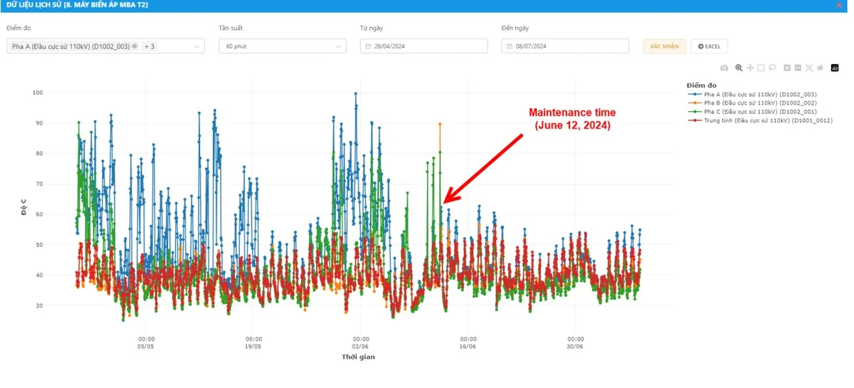
Temperatures on Phases A and C of Transformer T2's 110 kV bushing terminals climbed substantially above Phase B during evening peak loading, tripping the inter-phase delta-T threshold. Follow-up infrared imaging confirmed a copper-aluminum transition hotspot inside the terminal clamp. Because the anomaly developed during the evening load peak, daytime manual surveys had consistently missed it.
Incident 2 — Phase C Outgoing MCCB, Ao Hai Substation
The monitoring system flagged an accelerated thermal rise on Phase C of branch MCCB 2 in the 0.4 kV board. Field maintenance investigated on November 21, 2023 and verified high contact resistance. During a scheduled maintenance outage on November 27, 2023, the circuit was isolated, contact faces cleaned, and bolts torqued to specification. Upon re-energization, Phase C temperature returned to equilibrium — resolving the defect in less than one week with zero unscheduled customer outages.
Operational Lessons and Next-Generation Engineering Solutions
The 2023 pilot yielded key engineering insights that have been integrated into the current VTI-TS commercial product series:
| 2023 Pilot Observation | VTI-TS Engineering Enhancement |
|---|---|
| Requirement for de-energization during sensor installation or battery replacement. | Safety procedure preserved: installation occurs during planned de-energized windows. Outages for battery replacement eliminated: sensors harvest energy from conductor current and contain zero batteries. |
| Constrained space in compact LV cubicles hindered mounting external auxiliary CTs. | Dedicated current transformers are only required when full power quality metering is needed. VTI-TS sensors harvest magnetic energy natively from primary currents ≥ 1 A. |
| Network dropped packets when relying on 3G/4G cellular routers or substation Wi-Fi. | The GW22 / GW22-D gateway features industrial RJ45 Ethernet ports supporting Modbus TCP and MQTT over TLS directly to substation LANs. On-premise hosting ensures data sovereignty. |
Benchmarking Against IEEE 2969, CIGRE TB 999, and NFPA 70B
The pilot substations encompass three voltage classes (110 kV, 22 kV, and 0.4 kV). The table below compares the applicable international standards:
| Standard / Guide | Voltage Scope | Core Provisions | Deployment Alignment |
|---|---|---|---|
| IEEE Std 2969-2025 Guide for CTM of Switchgear and MCC up to 52 kV | ≤ 52 kV | Clause 1.2: CTM complements or replaces periodic thermography. Clause 5.3.1(d): monitoring lightly loaded joints. Clauses 5.5.1 / 5.6.1: sensors must preserve insulation ratings. Annex A.2: thermal trends are more critical than absolute accuracy. | 22 kV switchgear and 0.4 kV board at Ao Hai, including MCCB contacts (Incident 2). |
| CIGRE TB 999 (JWG B3.D2.62, 2026) Lifelong Supervision and Management of Substations | All voltage tiers | Table 2.8-1: recommends energy harvesting thermal sensors for transformer and circuit breaker thermal monitoring across HV-MV and MV-LV. Clause 1.2.4: notes strong industry migration from wired to wireless sensing. | 110 kV outdoor yard and Transformer T2 bushings at Hoi Hop (Incident 1) — above IEEE 2969's 52 kV limit. |
| NFPA 70B (2026 Edition) Standard for Electrical Equipment Maintenance | Industrial plants, utilities, and commercial facilities | Clause 7.2.1.2: permits permanently installed contact thermal sensors. Clause 7.4.5: continuous CTM satisfies periodic infrared thermography requirements under §§ 7.4.1–7.4.4. Clause 9.1.1.1: continuous monitoring justifies extended maintenance intervals. | 0.4 kV board at Ao Hai; vital for industrial facilities operating under NFPA 70B compliance programs. |
Critical Notice for Facilities Operating Under NFPA 70B: Under Sections 9.2.1.1–9.2.1.3, an unresolved high-priority thermal alarm shifts equipment from Condition 1 (60-month maintenance interval per Table 9.3.2) down to Condition 3 (reduced to 12 months). Nuisance alarms cause unnecessary maintenance expense. VTI's phase-comparison algorithm effectively screens out false alarms triggered by ambient weather or balanced load surges.
VTI-TS Continuous Thermal Monitoring Product Line
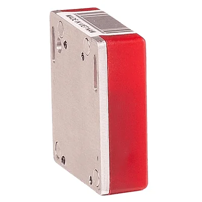
The current production VTI thermal monitoring system is built around the VTI-TS wireless sensor series (formerly TBR22) and the GW22 / GW22-D dual-band gateway hub.
| Specification | VTI-TS-22 | VTI-TS-26 |
|---|---|---|
| Primary Application | Metal-enclosed switchgear, MCC cubicles, 0.4 kV distribution boards | Outdoor substation yards, transformer bushings, disconnectors, line spans |
| Power Supply | Self-powered magnetic energy harvesting from conductor current, 100% battery-free, operating current ≥ 1 A. Battery-assisted variant available for de-energized points. | |
| High-Voltage Type Tests | Partial discharge < 10 pC at 500 kV (actual 8.7 pC per HVLAB test D04.24/BBTN-01). Lightning impulse withstand −1500 kV (HVLAB D12.23/BBTN-02, VILAS 491). | |
| Measurement Range | −40 to +125 °C | |
| Radio Communication | Bluetooth Low Energy 2.4 GHz, range ~100 m | LoRa AS923, line-of-sight range up to 3 km |
| Reporting Interval | Smart adaptive transmission, smart adaptive transmission based on thermal rate-of-rise | |
| Gateway Receiver | GW22 / GW22-D (dual-band): manages more than 1,000 sensors, Ethernet RJ45 output via Modbus TCP and MQTT for SCADA/DCS/BMS integration. | |
Frequently Asked Questions
What is Continuous Thermal Monitoring (CTM) in substations?
CTM uses permanently installed sensors to measure the temperature of electrical joints — busbar bolted connections, cable terminations, circuit breaker and disconnector contacts, transformer bushings — around the clock 24/7, replacing reliance on periodic infrared inspections. IEEE Std 2969-2025 provides technical guidance for CTM in switchgear and motor control centers up to 52 kV.
Which sensor type does CIGRE TB 999 specify for transformer and circuit breaker thermal monitoring?
Table 2.8-1 of CIGRE Technical Brochure 999 explicitly specifies 'energy harvesting thermal sensors' for the thermal monitoring requirements of transformers and circuit breakers across both HV–MV and MV–LV tiers. The VTI-TS series belongs directly to this specified category.
Can a continuous monitoring system replace infrared thermography under NFPA 70B?
Yes. NFPA 70B (2026 Edition) Section 7.4.5 permits permanently installed, continuous temperature monitoring devices to satisfy periodic infrared inspection requirements under Sections 7.4.1–7.4.4, provided the sensor system covers the critical connection points required in the inspection program.
How closely do wireless sensor readings match handheld thermal cameras?
In field evaluations across EVNNPC's Hoi Hop and Ao Hai substations, the difference between VTI contact sensors and handheld thermal cameras was between 0.4 and 3.2 °C. For asset maintenance and operations, the thermal trend over time and phase-to-phase delta-T provide far greater fault-detection reliability than single absolute spot measurements, as recognized in IEEE Std 2969-2025 Annex A.2.
Does sensor installation require a power outage?
Yes. VTI sensors are installed strictly when circuits are safely isolated, grounded, and verified de-energized during planned maintenance outages. Once installed, the devices operate for years without requiring any subsequent outage for battery replacements, because they harvest energy directly from the conductor's magnetic field.
What is the minimum line current required for VTI sensors to self-power?
VTI-TS magnetic energy harvesting sensors operate continuously when the primary conductor load current reaches 1 A or higher. For normally unenergized points such as earthing switches or open contacts, VTI provides long-life battery-assisted variants.
Publication Sources and Citations: This article is based on VTI Corp's empirical research report, originally published as "A Case Study of Substation Temperature Monitoring System" on Electrical Engineering Portal on January 5, 2026, updated with the latest commercial specifications and industry standard cross-references.
References:
[1] IEEE Std 2969-2025, IEEE Guide for Continuous Thermal Monitoring of Switchgear and Motor Control Centers up to 52 kV.
[2] CIGRE Technical Brochure 999, Lifelong Supervision and Management of Substations by Use of Sensors, Mobile Devices, Information and Communication Technologies, JWG B3.D2.62, August 2026.
[3] NFPA 70B, Standard for Electrical Equipment Maintenance, 2026 Edition.
[4] QCVN 26:2025/BCT, National Technical Regulation on Electrical Engineering — Power Grid, effective June 1, 2026.
Related Guides: Standards Compliance · Busbar Hot-Spot Monitoring · Continuous Thermal Monitoring & NFPA 70B · CBM & RBM Maintenance